Printed circuit board assembly is the point where an electronic design becomes a working product. A bare PCB provides the physical pathways for electrical signals, but it does not perform a function until components are accurately mounted, soldered, inspected, and tested. For manufacturers, engineers, startups, and procurement teams, understanding PCB assembly is essential because it directly affects product reliability, production cost, lead time, and long-term scalability.
TLDR: PCB assembly is the process of placing and soldering electronic components onto a bare printed circuit board to create a functional electronic device. The process usually includes design review, solder paste application, component placement, soldering, inspection, testing, and final quality control. Costs depend on board complexity, component selection, order volume, testing requirements, and turnaround time. A well-managed assembly process improves reliability, reduces defects, and helps products move efficiently from prototype to mass production.
What Is PCB Assembly?
PCB assembly, often abbreviated as PCBA, refers to the manufacturing process that turns a bare printed circuit board into a complete electronic assembly. The bare PCB contains conductive copper traces, pads, holes, and insulating layers, but it does not contain the electronic components needed to perform an actual function.
During assembly, components such as resistors, capacitors, microcontrollers, connectors, sensors, diodes, transistors, memory chips, and power management devices are attached to the board. Once these parts are soldered and verified, the assembly can be used inside products such as medical devices, industrial controllers, automotive electronics, consumer appliances, communication equipment, and aerospace systems.
A reliable PCBA is not simply the result of placing parts on a board. It depends on a controlled process, accurate documentation, qualified components, precise machinery, trained technicians, and thorough inspection. Even small errors, such as an incorrect resistor value or insufficient solder joint, can lead to intermittent failures or complete product malfunction.
The Main Types of PCB Assembly
There are several methods used in PCB assembly, and the right choice depends on the board design, component package types, production volume, and performance requirements.
Surface Mount Technology
Surface Mount Technology, or SMT, is the most common method used in modern electronics manufacturing. Components are mounted directly onto the surface of the PCB using solder paste and automated placement equipment. SMT enables compact designs, high component density, and efficient high-volume manufacturing.
SMT is widely used because it supports very small components and allows manufacturers to assemble complex boards quickly. Smartphones, computers, networking devices, and many industrial products rely heavily on SMT assembly.
Through Hole Assembly
Through hole assembly involves inserting component leads through holes drilled in the PCB and soldering them on the opposite side. This method creates strong mechanical connections and is often used for connectors, transformers, switches, and components that may experience physical stress.
Although through hole assembly is generally slower and less space-efficient than SMT, it remains important for applications where durability and mechanical strength are priorities.
Mixed Technology Assembly
Many modern boards use a combination of SMT and through hole components. This is known as mixed technology assembly. For example, a control board may use SMT components for processing and signal conditioning while using through hole connectors for external wiring.
Mixed assembly requires careful process planning because the board may need to pass through multiple soldering and inspection stages.
The PCB Assembly Process Step by Step
A professional PCB assembly process normally follows a structured sequence. Each stage helps reduce risk and ensure that the finished board meets the required performance standards.
- Design review and documentation check
- Solder paste application
- Component placement
- Reflow or wave soldering
- Inspection and quality control
- Functional testing
- Cleaning, packaging, and delivery
1. Design Review and Documentation Check
Before manufacturing begins, the assembler reviews the design files. These typically include Gerber files, a bill of materials, pick and place files, assembly drawings, and test requirements. This step is sometimes called a DFM review, meaning Design for Manufacturability.
The goal is to identify potential problems before production starts. Common issues include missing polarity marks, incorrect footprints, insufficient spacing between components, unavailable parts, unclear documentation, or thermal concerns. Correcting these issues early is far less expensive than discovering them after assembly.
2. Solder Paste Application
For SMT assembly, solder paste is applied to the PCB pads using a stencil. The stencil has openings that match the locations where components will be placed. A squeegee spreads solder paste across the stencil, depositing a controlled amount onto each pad.
This step is critical because too much or too little solder paste can cause defects such as bridging, tombstoning, weak joints, or open circuits. Precise solder paste printing is one of the foundations of high-quality assembly.
3. Component Placement
After solder paste is applied, automated pick and place machines position components onto the board. These machines use feeders, cameras, and programmed coordinates to place parts accurately and at high speed.
For prototype or low-volume work, some components may be placed manually, especially unusual connectors, large components, or parts that cannot be handled by automated equipment. However, automated placement is preferred whenever possible because it improves consistency and reduces human error.
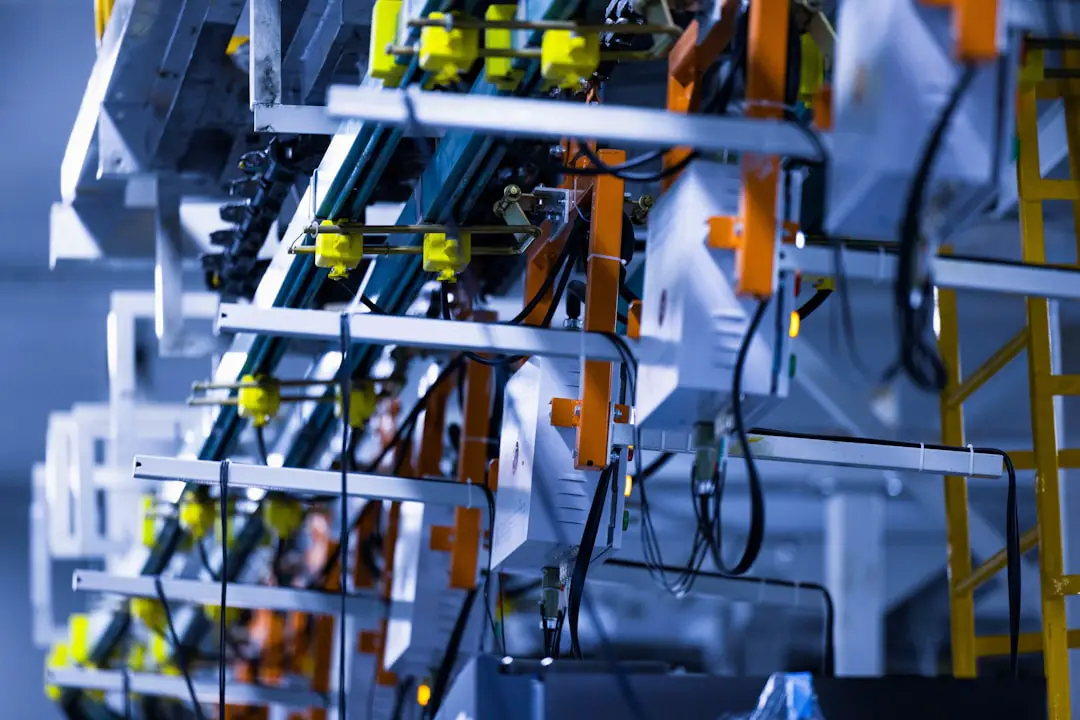
Image not found in postmeta4. Soldering
Once components are placed, the board passes through a soldering process. In SMT assembly, this is usually reflow soldering. The board moves through a controlled oven where the solder paste melts, forms joints, and then cools into solid electrical and mechanical connections.
For through hole components, manufacturers may use wave soldering, selective soldering, or manual soldering. Wave soldering passes the board over a wave of molten solder, while selective soldering applies solder only to specific areas. Manual soldering is often used for repairs, prototypes, or low-volume assemblies.
5. Inspection and Quality Control
Inspection is essential because many assembly defects are difficult to see without specialized equipment. Common inspection methods include:
- Visual inspection: A basic check for obvious defects, missing parts, reversed components, or poor solder joints.
- Automated optical inspection: Cameras compare the assembled board against expected component positions and solder joint characteristics.
- X ray inspection: Used for hidden solder joints, such as those under ball grid array components.
- First article inspection: A detailed review of the first completed board before continuing production.
These quality checks help verify that the assembly matches the design intent and that solder joints meet required standards.
6. Testing
Inspection confirms many physical aspects of the assembly, but testing confirms electrical performance. Depending on the product and risk level, testing may include in circuit testing, functional testing, boundary scan testing, power up testing, programming, calibration, or environmental stress screening.
Testing requirements should be planned early. A board that is not designed with test points or accessible programming connections may be harder and more expensive to verify. For regulated or mission-critical industries, robust testing is not optional; it is a fundamental requirement.
7. Cleaning, Packaging, and Delivery
Some assemblies require cleaning to remove flux residues or contamination. Others use no clean flux, which may not require washing under normal conditions. After cleaning and final inspection, boards are packaged in antistatic materials to protect them from electrostatic discharge, moisture, and physical damage.
Key Factors That Affect PCB Assembly Costs
PCB assembly pricing can vary significantly. A simple prototype may be relatively inexpensive, while a complex, high-reliability assembly can require substantial investment. Understanding cost drivers helps teams plan realistic budgets.
- Board complexity: More layers, tighter spacing, fine pitch parts, and dense layouts increase assembly difficulty.
- Component count: A board with hundreds of placements will generally cost more than a board with only a few components.
- Component availability: Shortages, long lead times, obsolete parts, or specialty components can increase cost and delay production.
- Assembly type: SMT is efficient at scale, while through hole and manual assembly often require more labor.
- Order volume: Higher quantities usually reduce the per unit cost because setup expenses are spread across more boards.
- Testing requirements: Functional fixtures, programming, calibration, and compliance testing add cost but also reduce field failure risk.
- Turnaround time: Expedited production typically costs more because it requires priority scheduling and faster procurement.
It is important to consider total cost, not just the quoted assembly price. A lower price may not be economical if it leads to poor yields, delayed shipments, excessive rework, or unreliable products in the field.
Typical Cost Structure
Most PCB assembly quotes include several cost categories. These may include engineering review, stencil fabrication, machine setup, component procurement, assembly labor, inspection, testing, rework, packaging, and shipping. For prototypes, setup costs can represent a large portion of the total. For higher-volume production, component costs often become the dominant factor.
A manufacturer may also charge for special services such as conformal coating, box build assembly, firmware programming, serialization, traceability documentation, or regulatory support. These services can be valuable when the product must meet strict reliability, safety, or compliance standards.
Benefits of Professional PCB Assembly
Working with a capable PCB assembly provider offers important benefits, especially for companies that do not have specialized manufacturing equipment or in-house electronics production expertise.
- Higher reliability: Controlled soldering, inspection, and testing reduce the risk of defects.
- Faster production: Automated equipment can assemble boards much faster than manual methods.
- Improved scalability: A design can move from prototype to larger production runs with a more predictable process.
- Technical feedback: Experienced assemblers can identify design issues that may affect manufacturability or reliability.
- Better quality control: Documented processes and inspection systems provide consistency across batches.
- Reduced internal burden: Companies can focus on design, sales, and product strategy instead of building manufacturing infrastructure.
How to Choose a PCB Assembly Partner
Selecting the right assembly partner should be based on more than price. A trustworthy manufacturer should demonstrate technical competence, clear communication, transparent quoting, and a disciplined quality process.
When evaluating providers, consider the following questions:
- Can they handle your component types, board size, tolerances, and production volume?
- Do they provide DFM feedback before assembly?
- What inspection and testing capabilities do they offer?
- How do they manage component sourcing and substitutions?
- Can they support traceability, documentation, and compliance requirements?
- What is their process for handling defects, rework, and corrective actions?
A good assembly partner should be willing to explain limitations, identify risks, and recommend practical improvements. Serious manufacturers understand that quality is created through process control, not confirmed only at the end of production.
Common Mistakes to Avoid
Many PCB assembly problems begin before the board reaches the factory. Incomplete documentation, unverified footprints, poor component sourcing decisions, and insufficient test planning can create avoidable delays and expenses.
Common mistakes include using unavailable components, failing to indicate component polarity, ignoring thermal management, placing parts too close together, not including test points, and ordering production quantities before validating prototypes. These issues can often be prevented through careful design review and communication with the assembler early in the project.
Final Thoughts
PCB assembly is a critical stage in electronics manufacturing. It combines engineering discipline, precision equipment, material control, and quality assurance to transform a bare circuit board into a working electronic product. Whether the project involves a small prototype batch or full-scale production, the quality of assembly has a direct impact on performance, reliability, and customer trust.
For the best results, teams should treat PCB assembly as a strategic part of product development rather than a simple purchasing task. Clear documentation, realistic cost planning, early manufacturability review, and appropriate testing all contribute to a smoother process and a stronger final product. In an industry where reliability matters, a careful and professional approach to PCB assembly is not just beneficial; it is essential.